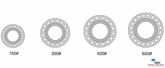
Tolerance Chart of High Alloy Steel Flanges
Alloy
Steel Flanges
Among
other products, alloy steel flanges are primarily composed of chromium,
molybdenum, and nickel. Corrosion and oxidation resistance are excellent on
these flanges. In water pipelines, oil and gas fields, chemical plants, and
food production systems, they are widely used.
Flanges
made of high alloy steel are a key driver for the automotive industry. In this
section, we will examine the current state of high alloy steel flanges and how
they will be used in the future. The most commonly used flange in an automotive
engine is a high alloy steel flange.
A minimum
of one piece is made from forged or extruded high-carbon tool steel. It is
common for these flanges to have a two-piece inner tube, with the outer portion
being welded to the inner tube. There are a number of performance and
non-structure features that can be added to any high alloy steel flange, as
well as structural features.
This
material’s strength and stiffness are entirely due to its rolled high carbon
tool steel composition, not just welded together. Additionally, the properties
that make these flanges ideal for this application are readily available in
standard flange elements. A number of factors influence the engineering design
and manufacture of high alloy steel flanges, including material cost, customer
specifications, manufacturing technology, and 3D CAD modeling.
Alloys with the following tolerances:
Its components include the RA 253 MA, RA330, RA333, ZERON 100,
AL-6XN, 304, 309, 316, 321, 347, 410, 446, 2205, 2507, 2101, 17-4, 15-5, and
800.
The tolerances listed were taken from ASTM A480
O.D. (Outside Diameter):
- When O.D. (Outside Diameter) is
less than 24″: ±1/16″ (1.6 millimeter)
- When O.D. (outside diameter)
exceeds 24 inches: 3.2 millimeters (1/8 inch).
Inside Diameter (I.D.):
- 10″ and below: ±1/32″ (0.8 mm)
- 12″ thru 18″: +1/8″ (3.2 mm)
- 20″ and greater: -1/16″ (1.6 mm)
Diameter of contact face
- 1/16″ recessed face: 1/32″ (0.8
mm)
- 1/4″ RF (Raised Face), T/G (Tongue
& Groove) (male & female), (m/f): 1/16″ (0.4 millimeters).
Diameter of hub at base
- When the hub base is 24″ or
smaller: 1/16″ (1.6 millimeters)
- When hub base is more than 24″,
add 1/8″ (3.2 millimeters).
https://thesteelexporter.com/tolerance-chart-of-high-alloy-steel-flanges/
#thesteelexporter #steelexporter #supplier #manufacturer #alloy #steel #flanges


Comments
Post a Comment